This discussion has been locked.
You can no longer post new replies to this discussion. If you have a question you can start a new discussion

Turning extra 6 LANS into "router" like links (UPDATE disconnects in 13-15 minutes loops)

Hey all I just finished up setting up the UTM 9 Home edition and I currently have it up and running with eth0 as the WAN and eth1 as the LAN. However, my motherboard has a total of 8 Ethernet ports (though 2 are being used for WAN and LAN out of the 8 - so 6 Ethernet ports open).

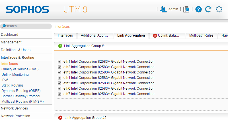
What I would like to do is be able to use those Ethernet ports (eth1-eth7) as a type of "router" switch. In other words, make them like a router has on the back of it where you can hook up more devices to it. I will be hooking them all into a 24 port switch (non-manage) and I would like to be able to unplug one of those eth1-7 plugs and still be able to get onto the internet with the other Ethernet ports as "backup" if possible.

So as an example of the above:

I have eth1 as the LAN and eth2. Both are plugged into the 24 port switch. I also have a PC hooked to that same 24 port switch. The PC has access to the internet and can surf the internet. However, lets say I need to unplug eth1 for a reason but still want the PC to have internet. I am wanting eth2 to take over to continue to feed the PC the internet while eth1 is unplugged.

Hopefully this can be done so I don't waste money buying a motherboard with a lot of extra Ethernet ports! [:)]

Thanks for your time.

David

UPDATE:

Hey all I have decided to track when and how long my current UTM 9 setup is messing up. Here is the flow:

Disconnects internet access (LAN and WIFI) every 13-15 minutes -> Takes about 25-30 seconds to come back -> repeats

It seems to be a constant 13-15min intervals when it disconnects and also a constant 25-30 seconds of nothing before it comes back online.

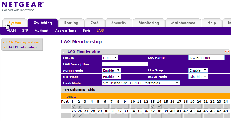
What setting(s) should I look for in my control panel in order to make sure I don't have a setting disabled or set up incorrectly for this type of issue to happen? Since I am using LAG and the netgear, how can I test to make sure its not the Netgear doing this? Is it the issue with this causing a broadcast storm?

And during the downtown this is what it shows now for the ping:


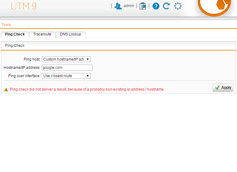
This thread was automatically locked due to age.
Parents
  • Even if you plug multiple ports into multiple switches to achieve fail-over for one (or more) PC's connected to the switch(es), your switches will need Spanning tree or they will suffer a broadcast storm.
    It's simply not possible with unmanaged "dumb" switches to connect them to each other with multiple connections.
Reply
  • Even if you plug multiple ports into multiple switches to achieve fail-over for one (or more) PC's connected to the switch(es), your switches will need Spanning tree or they will suffer a broadcast storm.
    It's simply not possible with unmanaged "dumb" switches to connect them to each other with multiple connections.
Children
  • Even if you plug multiple ports into multiple switches to achieve fail-over for one (or more) PC's connected to the switch(es), your switches will need Spanning tree or they will suffer a broadcast storm.
    It's simply not possible with unmanaged "dumb" switches to connect them to each other with multiple connections.


    Alright would a Dell PowerConnect 2724 managed switch do the trick then?
  • Alright would a Dell PowerConnect 2724 managed switch do the trick then?


    From what I quickly read it supports link aggregation and VLAN's, so it will probably also support spanning tree.
    I think however that link aggregation (LAG) is the choice you want; it effectively bundles multiple physical connections to 1 logical connection.
  • From what I quickly read it supports link aggregation and VLAN's, so it will probably also support spanning tree.
    I think however that link aggregation (LAG) is the choice you want; it effectively bundles multiple physical connections to 1 logical connection.


    Looking around the forums for "Link Aggregation" seem to come up with needing the switch to feature VLANs - is that correct? If so then I would still need a managed switch in order to pull what I want to pull off. If not then please do explain. [:)]
  • Looking around the forums for "Link Aggregation" seem to come up with needing the switch to feature VLANs - is that correct? If so then I would still need a managed switch in order to pull what I want to pull off. If not then please do explain. [:)]


    No, you don't need both. Link aggregation simply bundles multiple interfaces. UTM supports it and if your switch also supports it, I think it is what you want. VLANS are totally different in that they segregate multiple broadcast domains. Hosts in one VLAN cannot communicate with hosts in another unless a router routes traffic between the VLAN's.
  • From what I quickly read it supports link aggregation and VLAN's, so it will probably also support spanning tree.
    I think however that link aggregation (LAG) is the choice you want; it effectively bundles multiple physical connections to 1 logical connection.


    It looks like the DELL 2824 has this to say about LAG:
    IEEE 802.3ad — Link aggregation with static LAG support


    So is that what i need in order to bundle all 7 ports and send 7 Ethernet cables to the Dell 2824?
  • To draw it out with what i am wanting to do:

    ===========================================================
    |   Intel ATOM motherboard with 8 LAN's (1 WAN / 7 LAN)   |
    |     [eth0][eth1][eth2][eth3][eth4][eth5][eth6][eth7]    |
    ========[]====[]====[]====[]====[]====[]====[]====[]=======
            ^     |     |     |     |     |     |     |
            |     |     |     |     |     |     |     |
            |     v     v     v     v     v     v     v
            |  ===========================================================
            |  |        Managed 24 port gigabyte switch (LANS)           |
            |  |[ 1 ][ 2 ][ 3 ][ 4 ][ 5 ][ 6 ][ 7 ][ 8 ][ 9 ][10][11][12]|
            |  |[13 ][14 ][15 ][16 ][17 ][18 ][19 ][20 ][21 ][22][23][24]|
            |  ===========================================================
            |            ^          ^          ^          ^          ^
            |            |          |          |          |          |
            |            v          v          v          v          v
            |        ===========================================================
            |        |       UN-Managed 24 port gigabyte switch (LANS)         |
            |        |[ 1 ][ 2 ][ 3 ][ 4 ][ 5 ][ 6 ][ 7 ][ 8 ][ 9 ][10][11][12]|
            |        |[13 ][14 ][15 ][16 ][17 ][18 ][19 ][20 ][21 ][22][23][24]|
            |        ===========================================================
            |          |            |          |             |         |
            |          v            v          v             v         v
            |          [out PC1]   [out PC2] [out WiFi] [out PC3]  [out PC4]
            |
            [Internet Connection (WAN)]

    So the Intel ATOM motherboard is the motherboard that houses the 8 LAN ports. eth0 is the WAN while eth1-7 are the LANs.

    Those 7 LANs go out to the Managed switch (on random ports).

    Then the remaining Managed switch ports (17 ports) are used for connecting computers, etc. Five (5) out of those 17 ports that are left on the Managed switch will connect the other UN-managed switch so that those can be populated with connecting computers, etc.

    So that if eth6 gets disconnected for whatever reason, the rest of the eth1-5, 7 still operate normally for the 2 switches (as in, allows DHCP connections to still stay alive for all computers, etc that are connected to both switches.

    Hopefully doing this above show more of the detail that I am currently going for in my setup.


    If you also connect an unmanaged switch multiple times to the managed switch as you describe you will have a problem on the unmanaged switch! You'll create switching loops and the unmanged switch will get into a broadcast storm, so don't do this with unmanaged switches!
    And also I don't see why you would bundle 7 interfaces together.... Two would normally be more than enough for redundancy escpecially when you only have one UTM.
  • Thanks for all the reply's to my question everyone.

    It looks as though i will be purchasing the Netgear ProSafe GSM7248 v2 switch and not using the 24 port un-managed one since this one comes with 48 ports-that should be enough for my home use. [:)]

    The specs of the Netgear ProSafe GSM7248 v2 are:

    Layer 2 Services
    ========================================
    – IEEE 802.1Q static VLAN (1024)
    – IEEE 802.1p Class of Service (CoS)
    – IEEE 802.1D Spanning Tree Protocol
    – IEEE 802.1v Protocol VLAN & Port VLAN and MAC-based VLAN
    – Voice VLAN
    – Guest VLAN
    – IP subnet-based VLAN
    – IEEE 802.1 Q-in-Q
    – IEEE 802.1w Rapid Spanning Tree
    – IEEE 802.1s Multiple Spanning Tree
    – IEEE 802.3ad Link Aggregation (LACP)
    – IEEE 802.1x port access authentication
    – IGMP v1, v2, v3 snooping support
    – IGMP querier
    – Static multicast filtering
    – Ingress rate limit in 1 Kbps increments
    – Weighted round robin (WRR) queue technology
    – MLD v1, v2 snooping

    Layer 3 Services
    ==========================================
    – Static routing
    – ARP
    – System memory: 128 MB
    – Packet buffer memory: max support 1.5 MB buffer memory
    – Code storage (flash): 32 MB
    – Address database size: 8 K media access control (MAC) addresses
    – Number of VLANs: 1024 (1-4093)
    – Number of trunks: 64
    – Number of queues: 8
    – Number of static route: 32
    – Number of routed VLANs: 32
    – Number of ARP entries: 480
    – Number of ACL rules: 224

    Network Standards Compatibility
    ==========================================
    – IEEE 802.3i 10BASE-T
    – IEEE 802.3u 100BASE-TX, 100BASE-FX
    – IEEE 802.3ab 1000BASE-T
    – IEEE 802.3z 1000BASE-X
    – IEEE 802.3x flow control


    Please let me know if this managed switch has the features as well that I will be needing.